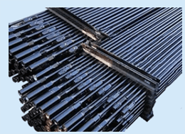
Pumping Unit Parts

  • Product Code:
  • Color:
  • Price:
  • Clicks:
  • Date: 2016-02-26 10:42:21

Pumping unit wire

Both ends of the wire is made of steel wire rope, a rope socket, hang after bending the donkey head rope frame, lower suspension beam hanger. The wire rope for multilayer don't reverse the wire rope.
Note: should be regularly check the wire position should not have broken strands and loose rope socket.


Beam hanger
 Beam hanger is a tool for connecting the polished rod and wire.

This pumping unit beam hanger is monomer type beam hanger.

The polished rod of beam hanger hanging from the hanging cord, sitting on the beam hanger has polished rod slip.


Polished rod slip
 

Polished rod slip is fixed and the polished rod with tools, it puts the whole after polished rod fixed beam hanger.

 My factory supporting factory polished rod slip for hinge joint, with pore size 25 (1) and the aperture 28 (1 1/8 ") in two specifications.


The donkey head pin
 

Donkey head pin is connected beam and the head of the parts, the donkey head pin in lubricating oil hole.

Should note: regular filling grease, in order to prevent the beam on the shaft sleeve and the donkey head pin connection of rust.


Support bearing
 

Support inside the bearing seat is equipped with two pay 42240 roller bearings, lubricated by grease. When mounted pumping unit, the bearing should be sufficient grease.

 Support bearing assembly under beam, sitting on the support shaft seat.


Beams bearing
 

Beam is equipped with a pair of 3632 self-aligning bearing housings, grease lubrication. When mounted pumping unit, bearing should add grease.

Beams bearing assembly in the beam at the back of the lower part, and connected to the beam support.


pitmanpin

pitmanpin is connected to the beam and connecting rod parts,  pitmanpin with lubricating oil hole.

Should note: regular filling grease, in order to prevent the connecting rod head, beam axle sleeve and pin shaft link of rust.


Connecting rod

Connecting rod is made of seamless steel tube and the upper and lower connecting rod head welded together.

On the shaft sleeve are installed in the connecting rod head, has the corrosion resistance, with connecting rod shaft pin can be used to prevent rust.

Connecting rod head through the connecting rod shaft pin connected to the beam, the crank and connecting rod head installation device, for the hole plate structure, reliable connection and easy to install and disassemble.

Note: should be regularly check weld position of the connecting rod head up and down, can not have crack, otherwise should repair or replace the connecting rod.


Crank pin device

In the crank pin device is equipped with a pair of 3624 self-aligning bearings, mining with grease lubrication. When mounted pumping unit, the crank pin device should add grease.

Crank pin and crank of installation, the installation outside the crank pin device has connecting rod.

Crank pin through the crank set connected to a crank.

Crank pin and crank pin set shall not be less than 85%, the contact area and per sq. miles obsessed should contact point.

Crank pin and crank pin nut is about spin (positive and negative) thread.

Special note: rotating direction of the beam pumping unit for pumping unit crank down to the front of the pumping unit, thus when installation, from the mouth of the well direction for pumping unit, left-hand button (DE) crank pin installed on the left of the pumping unit, the right button (positive) crank pin, installed on the right side of the beam pumping unit, can not be wrong.

Special note: the crank pin nut shall not loose, must always check the fastening, in order to prevent accidents.


Crank

Crank for cast iron pieces, weight and center of see table 1.

Crank installed on both sides of the reducer output shaft, a wedge bonding wedge, each have two differential bolts on each of the crank, the crank lock on the reducer output shaft.

Three crank crank pin hole, crank shaft is installed on the different crank pin hole, can get different pumping unit stroke, see table 1.

With a rack on the crank balance piece and is equipped with a crank. With the aid of gear pumps, by adjusting the position of the crank balance weight on the crank, can obtain different balance effect, to find the best balance condition.


reducer

Reducer is symmetric shunt type two levels of double circular arc helical teeth and herringbone gear tooth cylindrical gear reducer, specific parameters are shown in table 1.

Reducer adopts type extreme pressure industrial gear oil, gear oil pool leaching oil lubrication, drive shaft bearing with gear oil splash lubrication, intermediate shaft and driven shaft bearing relies on oil supply lubrication oil scraper plate.

On the deceleration box body is equipped with the oil level indicating hole, in order to check the oil level.

Installed on the base of cylinder speed reducer, the output with the crank shaft at both ends and the left side brake mechanism of input shaft, the input right end is equipped with big belt wheel, power transmission device as the power input terminal.

Note: eight sets of gear reducer must be regularly check fastening bolt and nut installed, shall not be loose.

Note: reducer intermediate shaft and output shaft of a oil groove on the bearing end cover, when maintenance should pay special attention to cover the installation position of tank, shall not be blocked oil, otherwise it will cause bearing oil shortage, the intermediate shaft bearing damage or output shaft bearing.

Special note: should be regularly check reducer output shaft at both ends of the brake wheel and the big belt wheel fastening, not loose, to avoid the accident.


The brake safety device

Brake safety device for the pumping unit during transportation, installation, operation and maintenance downtime and Settings, the safety of the installation in reducer intermediate shaft bearing cover of the case.

In the operation and maintenance downtime, tighten the brake, also should be insurance card block block device, card into the brake hub flange card slot, to stop pumping unit movement, to ensure safety.

Note: must be the card before starting the block up, loosen the brake. Otherwise, it will damage the motor.

Special note: should be regularly check the brake safety gear shaft, shaft fixed bolt, intermediate shaft bearing cover etc, should be safe and reliable, can not have any crack and damage.

The brake mechanism

Using external contracting brake type structure, brake wheel Ø 400 mm diameter.

The brake wheel is steel, the installation on the left side of the reducer input shaft. Brake linings for steel castings, the inside is equipped with lining, installed on the reducer box cover.

Brake mechanism for a set of operating mechanism are connected by a rigid bar. On the brake handle, the end connection by splicing bearing, change direction, and speed reducer drive shaft at the left brake mechanism of the brake lever.

Brake linings with brake mechanism of the brake lever to drive, with the brake lever clamp, hold the brake wheel brake.

Brake lever and the seat back, easy to manipulate the brake.

Note: the operating brake force should be flat, not on the brakes.


Recommended